
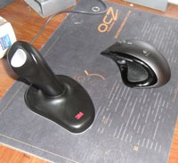
 3M makes a joystick shaped ergonomic mouse that I find really comfortable to use. The only problem with it is that it uses a crappy 400dpi optical engine straight out of 2001. This leaves me in the unfortunate situation where I have to have two mice, a comfortable one for web browsing, and an uncomfortable but precise one for serious work and gaming.
Because the 3M Ergonomic mouse sells for $50 or so, I felt uncomfortable taking mine apart to see if it could be improved. Finally, opportunity knocked, and I got my hands on a 3M mouse that was slightly broken.
I decided to do a heart transplant. Take the case of the 3M, and transplant in the circuitry of a modern mouse. The project had a few setbacks. The first mouse I bought, a Logitech RX1500 laser mouse, broke while I was modifying it for the project. The second mouse had several problems, the biggest of which was that the circuit board was too big to fit in the 3M case. Finally, I settled on an excellent HP “Wired Laser Mini Mobile Mouse” (Newegg), a 1,600dpi mouse that was small enough to fit easily into the 3M enclosure, and also quite cheap.
I’m posting this tutorial in case anyone wants to try a similar conversion on their own 3M mice, or on any other object for that matter. Having taken apart three different mice, I can say that they are pretty easy to modify. If you are considering your own retrofit project, make sure you use a laser mouse, not an optical mouse. Optical mice use focused light from an LED, meaning that the optical element has to be positioned with sub-millimeter accuracy in order for it to work correctly. Lasers don’t need to be focused, so laser mice are much more flexable in terms of how they are positioned. This is very important if you plan on using the mouse’s circuitry outside of the original enclosure.
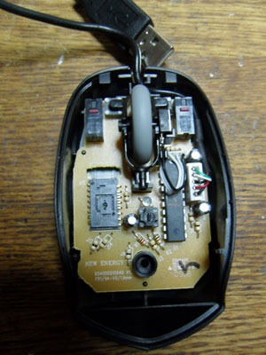
The first step was disassembling the 3M mouse. The grey bottom plate comes off easily with one screw, but the “joystick” handle is much harder. It technically twists off, but the latches holding it on are quite delicate, and you will probably break a few. This is ok as it can be glued back together when you are done. I also took the joystick apart, but this turned out not to be necessary. Save the metal weights, they will be useful later. The circuit board itself, as you can see, is VERY simple, and the optical engine is about as low end as you can get. How 3M justifies charging $50 for this, I don’t know.
The wiring for the buttons is very simple. There is a ribbon cable coming down with four wires. One is a common ground, the others each go to one switch, left click, right click, and center click. Easy testing with a multimeter can tell you which is which. The ribbon cable is soldered to the circuit board. I cut the cable and soldered on a standard pin connector so that I could disconnect and reconnect the joystick while testing the new mouse.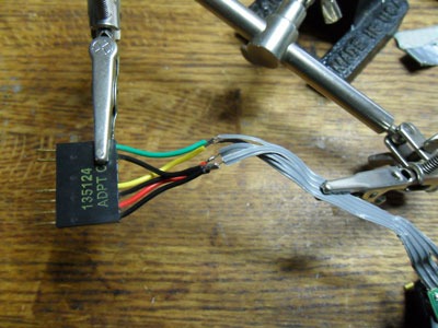
Finally, the mouse is down to its bare components. I took my trusty dremel and sanded down the various plastic ridges on the base that were used to position the original components, creating a flat mounting point for the new circuitry.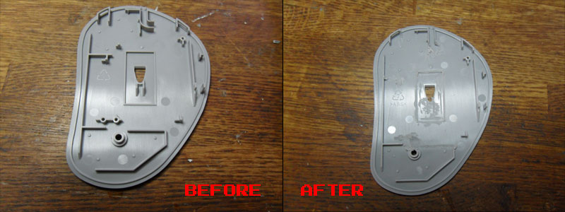
Now its time to dissect your donor mouse. The HP mouse also opened easily with one screw. Inside, you can see the small circuit board, and the scroll wheel mounted on top. Luckily the scroll wheel’s cable is detachable, you can take it off and the mouse still works fine (I haven’t found a mouse that doesn’t work with the scroll wheel removed). I was hoping to Dremel a hole for the scroll wheel somewhere on the 3M, but as it turned out there was very little room inside, and nowhere to put the scroll wheel where it would be useful.
Next, I had to wire up the buttons on the HP circuit board to connect to the ones on the 3M mouse. You can chose to desolder the original switches, or as I did, leave them on there and run the 3M switches in parallel. The switches are standard SPST momentary switches with a common ground on the circuit board. I soldered wires to the appropriate pads and ran them to a matching connector to the one on the 3M buttons. Everything worked fine on the first try.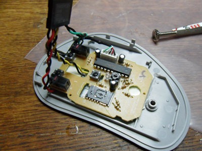
Now I had to get everything into the 3M mouse body. As it turned out, I needed to drill a new hole on the bottom for the HP’s optical element. The HP’s circuit board is held down with industrial 3M double sided foam tape. I added the weights back into the mouse (plus a few more because I like a slightly heavier feel to my mice), connected the buttons up, screwed everything back together.
The HP Laser mouse’s DPI is adjustable, and it remembers its DPI setting even if you unplug it. This is good because I did not drill a hole for the DPI adjustment switch, you have to disassemble the mouse not to change it. I leave it on 800 DPI, to match the feel of my fancy Logitech MX Revolution.
The new franken mouse looks and feels almost exactly the same as the original, but using it is like night and day. Its now responsive on any surface, with good speed and precision. I have even started using it for work on occasion (I still prefer the Logitech for gaming). For a relatively quick project, I am very happy with the results.
Mahesh Sawaiker August 6, 2020
I cant believe this has not even a single comment :),. I have run into a similar problem, will try this.
John May 30, 2025
Great article. Now I understand why the mouse sensitivity is so bad.
Can you detail the mouse button and removal a little more? I need to replace the left switch.
Jozer99 June 9, 2025 — Post Author
There are already wires coming down from the left and right buttons in a ribbon cable. Using a multimeter you can figure out which wires connect to which switch on the joystick. I then connected these wires in parallel with the switches on the new mouse circuit board. You can do that by just soldering the two wires from the joystick switch to the two pads where the switch on the circuit board connects. You can leave the old switches on the circuit board, or remove them to free up more space. Removing them may be tricky, unless you have a hot air desoldering station and some experience with it, I recommend leaving them be.
John June 15, 2025
You misunderstand, I have unscrewed the 4 screws holding the joystick to the base and and I need to disassemble it to replace a broken left switch. Can you give any guidance to reduce the chance of breaking the clips?
btw my joystick mouse is all black 5V 100mA ©2011 with a single hockey stick shaped weight and 2 x JST PH 4-Pin (2mm pitch) connectors. CON1 (R, W, Bu, G) for USB cable and CON-2 for joystick switches labelled (wire colour): GD (Bu), LB (Bk), MB (R), RB (G).